CERES® 800V
- Developed for vertical electrical sounding (VES)
- Scheme-based and free-form measurement, session management
- Live display of the VES curve
- One-button measurement and data export
From vertical electrical sounding to 2D tomography and induced polarization — a simple, rugged and lightweight resistivity system designed for fieldwork.

The area below is the real CERES® interface, connected to a server running in simulation mode. Browse the menus, open a measurement session, explore the screens. Click to start: the demo opens full screen.
The instrument works like a server. Connect from a tablet, phone or computer with a web browser — no app to install.

The switching electronics sit in the reel's hub. Each reel carries 8 electrode outlets; reels can be added to the system in any order.

Before measuring, electrodes are checked in pairs; poorly connected or disconnected electrodes are listed.
Watch the table, VES curve and pseudosection as you measure; geometric factor and apparent resistivity are computed instantly.
Self-potential (SP) is compensated automatically. Stack 1, 2, 4 or 8 times; standard deviation is shown and stored. Quality is checked automatically via an S/N calculation over the full time series.
An emergency-stop button cuts the current, and current output is only allowed with the button released. The battery input is reverse-polarity protected.
Attach the 12 V battery and measurement cables; the instrument boots in 15–30 seconds.
Open the interface over Wi-Fi from a tablet or phone, detect the cables and run the contact test.
Choose the array, current and stacking. Start with a VES scheme or a tomography template.
Data files are saved to the instrument's memory automatically; copy them via USB to your processing software.
Aquifer and layer detection with vertical electrical sounding.
Resistivity and induced polarization for ore and raw-material surveys.
Non-destructive imaging of buried structures and voids.
Sub-foundation conditions, layer thickness and ground variation.
Mapping reservoirs and fault zones with resistivity sections.
Identifying slip surfaces and discontinuities in 2D sections.
The values below are taken from the CERES 800M-WiFi specification sheet. For specific values of CERES-800V and CERES-800W, please contact us.
| Case / dimensions | Shock- and weather-resistant plastic case; 49 × 39 × 19 cm |
|---|---|
| Display | 11″ tablet |
| Weight | 8.3 kg |
| Memory | 16 GB built-in; 128 GB on the tablet |
| Operating system | Web-based Turkish / English interface; upgradable |
| Connectivity | Wi-Fi |
| Electrode count / spacing | 8-electrode outlets, cables can be added as needed; standard spacings 1, 5 and 10 m |
| Cable type | PUR cable wound on a reel |
| Electrode switching | External switching units integrated into each reel, each controlling 8 electrodes |
| Arrays | Wenner, Schlumberger, Dipole-Dipole, Pole-Dipole, Pole-Pole, Gradient and user-defined custom arrays |
| VES measurements | User-defined schemes and free-form measurement; live plotting of the VES curve |
| ERT measurements | Automatic measurement settings; data logging with quality indicators; live pseudosection view |
| Contact resistance | Electrode contact resistance measured before each survey and stored in the data file |
| Output power | 800 W |
|---|---|
| Output current | 5 – 2000 mA, user- or system-adjustable |
| Output current waveform | Square wave with adjustable period (1–8 s) |
| Output voltage | 1600 V (p-p) |
| Power supply | 12 V / 60 Ah battery (generators not supported) |
| Safety | Emergency-stop button cuts current instantly |
| Protection | Reverse-polarity protection |
| Input range | ±20 V |
|---|---|
| A/D converter | 24 bit / 1 µV sensitivity |
| Sampling rate | 20 kS/s |
| 50 Hz filter | Yes |
| SP removal | Automatic |
| Stacking | S/N-controlled automatic stacking or user-defined stacking (1–8) |
| Cable type | Passive cable wound on reels, 8 outlets per reel |
|---|---|
| Electrode spacing | Standard 1, 5 and 10 m; custom spacings such as 3 and 20 m on request |
| Cable material | Field-durable PUR |
| Connectors | Military-standard connectors |
| Electrode | 40 cm steel electrode (hexagonal) |
|---|---|
| Power cable | Battery connection cable |
| User manual | Detailed instrument manual |
| Warranty | 2 years (manufacturing defects and faults, excluding user error) |
CERES-800M measures with Wenner, Schlumberger, Dipole-Dipole, Pole-Dipole, Pole-Pole and Gradient arrays; user-defined mixed arrays can also be produced from the instrument interface via a script. Cables come in 8-electrode reels and are joined end to end to reach up to 256 electrodes in effective use.
| Electrode spacing | Standard 1, 5, 10 m (custom spacings such as 3, 20 m on request) |
|---|---|
| Electrodes per cable | 8 |
| Max. electrodes | 256 |
| Switching | External switching unit integrated into the reel |
| Outer jacket | PUR |
Electrode spacing is made with a ±10% tolerance; for example, an 8-electrode reel with 10 m spacing is 88 m long.

The server inside the instrument serves an HTML/CSS/JavaScript interface over Wi-Fi to tablets, phones or computers. It is platform-independent and comes in dark and light themes.
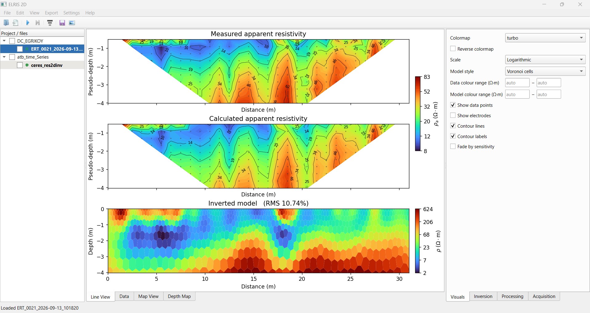
We use our own ELRIS 2D software to process field data: it compares measured and calculated apparent-resistivity pseudosections, produces the 2D inversion model and reports the RMS misfit.
ELRIS 2D is a separate desktop application developed by LARES, used to process data collected with CERES®.
CERES® generates high current and voltage while operating. While current is applied, the operator and bystanders must stay away from and not touch electrodes and cables. Details are in the user manual.
Tell us your application; we will reply with a model, cable and accessory recommendation.